TGOV1
Steam turbine-governor model.
Block Diagram
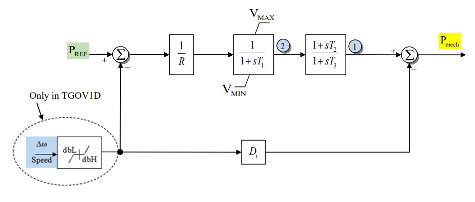
Figure 1: Governor TGOV1 model. Figure courtesy of PowerWorld
Model Parameters
Symbol |
Units |
JSON |
Description |
Typical Value |
Note |
|---|---|---|---|---|---|
\(T_{\mathrm{rate}}\) |
[MVA] |
|
Governor component power base |
100.0 |
|
\(R\) |
[p.u.] |
|
Permanent droop |
0.05 |
|
\(T_1\) |
[s] |
|
Steam-bowl time constant |
0.5 |
|
\(T_2\) |
[s] |
|
Turbine numerator time constant |
2.5 |
|
\(T_3\) |
[s] |
|
Reheater time constant |
7.5 |
|
\(P_\mathrm{v}^{\max}\) |
[p.u.] |
|
Maximum valve position |
1 |
|
\(P_\mathrm{v}^{\min}\) |
[p.u.] |
|
Minimum valve position |
0 |
|
\(D_\mathrm{t}\) |
[p.u.] |
|
Turbine damping coefficient |
0 |
Parameter Validation
A valid TGOV1 parameter set must satisfy the following conditions:
Set \(T_{\mathrm{rate}}\) equal to the connected machine MVA base. A zero component power base is not supported.
Model Derived Parameters
Let \(\epsilon_T=10^{-3}\ \mathrm{s}\). A time constant below \(\epsilon_T\) is raised to that floor in place, so every equation below uses the raised value:
Model Ports
Name |
Port |
Init |
Description |
|---|---|---|---|
|
Input |
Known |
Machine speed deviation; optional, defaults to zero |
|
Input |
Unknown |
Governor reference; optional |
|
Output |
Known |
Mechanical-power signal seeded by the machine |
Model Variables
Internal Variables
Differential
Symbol |
Units |
Description |
Note |
|---|---|---|---|
\(P_\mathrm{v}\) |
[p.u.] |
Valve position |
Component base |
\(P_\mathrm{t}\) |
[p.u.] |
Turbine-block output |
Component base |
Algebraic
Symbol |
Units |
Description |
Note |
|---|---|---|---|
\(P_\mathrm{m}\) |
[p.u.] |
Mechanical-power output |
System base; read by the machine model |
External Variables
Differential
Symbol |
Units |
Description |
Note |
|---|---|---|---|
\(\omega\) |
[p.u.] |
Machine speed deviation |
Optional |
Algebraic
Symbol |
Units |
Description |
Note |
|---|---|---|---|
\(P_\mathrm{ref}\) |
[p.u.] |
Governor reference |
Component base; optional |
Model Equations
Smooth functions: antiwindup.
For readability, define:
Internal Equations
Differential
Algebraic
External Equations
None.
Initialization
The machine provides \(P_\mathrm{m}\) on system base:
Initialization rejects \(P_\mathrm{v}\) outside the configured valve limits.
Monitors
None.