REGCA
REGCA is a first-generation WECC renewable generator/converter model for inverter-coupled resources.
Notes
None.
Block Diagram
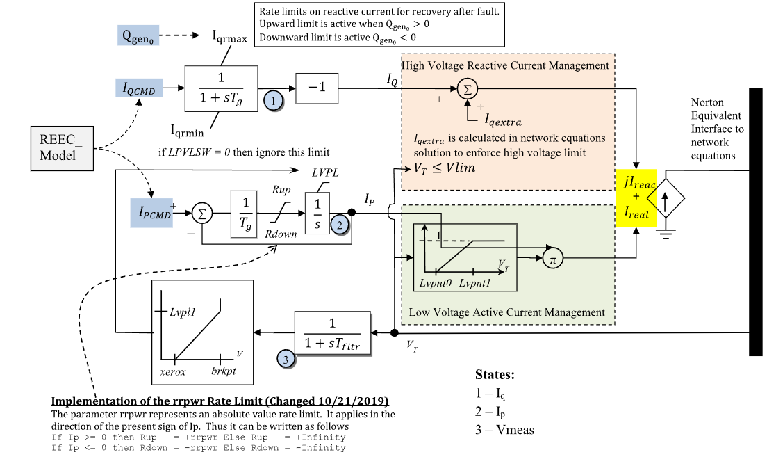
Figure 1: REGCA generator/converter model. Figure courtesy of the PowerWorld REGC_A model reference.
Model Parameters
Symbol |
Units |
JSON |
Description |
Typical Value |
Note |
|---|---|---|---|---|---|
\(P_0\) |
[p.u.] |
|
Initial active power injection |
1.0 |
System base; required initialization source |
\(Q_0\) |
[p.u.] |
|
Initial reactive power injection |
0.0 |
System base; required initialization source |
\(S^\mathrm{base}\) |
[MVA] |
|
REGCA component power base |
100.0 |
|
\(T_\mathrm{g}\) |
[s] |
|
Converter current-control lag time constant |
0.02 |
|
\(T_M\) |
[s] |
|
Terminal voltage sensor time constant |
0.02 |
Source label: |
\(R_q^{\max}\) |
[p.u./s] |
|
Reactive-current recovery positive rate limit |
999.0 |
Source label: |
\(R_q^{\min}\) |
[p.u./s] |
|
Reactive-current recovery negative rate limit |
-999.0 |
Source label: |
\(R_p^{\max}\) |
[p.u./s] |
|
Active-current magnitude recovery rate limit |
999.0 |
Source label: |
\(s_L\) |
[binary] |
|
LVPL switch |
1 |
Source label: |
\(I_{L1}\) |
[p.u.] |
|
LVPL upper-current ceiling |
1.1 |
Source label: |
\(V_{L0}\) |
[p.u.] |
|
LVPL zero-crossing voltage |
0.4 |
Source label: |
\(V_{L1}\) |
[p.u.] |
|
LVPL upper breakpoint voltage |
0.9 |
Source label: |
\(V_{A0}\) |
[p.u.] |
|
LVACM lower breakpoint voltage |
0.4 |
Source label: |
\(V_{A1}\) |
[p.u.] |
|
LVACM upper breakpoint voltage |
0.9 |
Source label: |
\(V_\mathrm{hv}^{\max}\) |
[p.u.] |
|
HV reactive management activation threshold |
1.2 |
Source label: |
\(Q^{\min}\) |
[p.u.] |
|
PowerWorld compatibility field |
Optional; accepted but unused |
|
\(K_\mathrm{hv}\) |
[p.u.] |
|
HV reactive management gain |
0.7 |
Optional; defaults to 0.7; block name: |
\(X_\mathrm{e}\) |
[p.u.] |
|
PowerWorld compatibility field |
Optional; accepted but unused |
All listed JSON parameters are required unless marked optional.
Parameter Validation
A valid REGCA parameter set must satisfy the following conditions:
Time constants below \(\epsilon_T\) are raised to \(\epsilon_T\) and logged as a warning, every other condition is a configuration error.
Model Derived Parameters
The fixed slope \(K_L\) [p.u./p.u.] approximates the unbounded LVPL characteristic above \(V_{L1}\).
Model Ports
Name |
Port |
Init |
Description |
|---|---|---|---|
|
Bus |
Known |
Terminal bus voltage |
|
Input |
Unknown |
Active-current command input |
|
Input |
Unknown |
Reactive-current command input |
|
Output |
Known |
Branch-current real-component output |
|
Output |
Known |
Branch-current imaginary-component output |
|
Output |
Known |
Branch active-power output |
|
Output |
Known |
Branch reactive-power output |
Model Variables
Internal Variables
Differential
Symbol |
Units |
Description |
Note |
|---|---|---|---|
\(V_M\) |
[p.u.] |
Filtered terminal voltage |
State 3 in Fig. 1 |
\(I_q\) |
[p.u.] |
Reactive-current state |
State 1 in Fig. 1 before the |
\(I_p\) |
[p.u.] |
Active-current state |
State 2 in Fig. 1; component base |
Algebraic
Symbol |
Units |
Description |
Note |
|---|---|---|---|
\(V_T\) |
[p.u.] |
Terminal voltage magnitude |
|
\(I_r\) |
[p.u.] |
Branch-current real component |
System base |
\(I_i\) |
[p.u.] |
Branch-current imaginary component |
System base |
\(I_q^\mathrm{extra}\) |
[p.u.] |
Extra inductive current from high-voltage reactive current management |
Component base |
\(I_L\) |
[p.u.] |
LVPL upper-limit current curve |
Component base; function of \(V_M\) |
\(P^\mathrm{br}\) |
[p.u.] |
Branch active power |
System base |
\(Q^\mathrm{br}\) |
[p.u.] |
Branch reactive power |
System base |
External Variables
Differential
None.
Algebraic
Symbol |
Units |
Description |
Note |
|---|---|---|---|
\(V_r\) |
[p.u.] |
Terminal voltage, real component |
Bus input |
\(V_i\) |
[p.u.] |
Terminal voltage, imaginary component |
Bus input |
\(I_p^\mathrm{cmd}\) |
[p.u.] |
Active-current command in the terminal-voltage reference frame |
Optional signal port |
\(I_q^\mathrm{cmd}\) |
[p.u.] |
Reactive-current command in the terminal-voltage reference frame |
Optional signal port |
Model Equations
Smooth functions: clamp, linseg, max, min, \(\rho\).
Define the pre-limit current derivatives:
Figure 1 places LVPL on the active-current integrator ceiling, realized by
the awmax gate in the differential equations. The ceiling moves with the
sensed voltage, and a pinned \(I_p\) tracks it as a non-windup limit. rrpwr
applies the active-current recovery rule according to the sign of \(I_p\).
The limited active-current integrator drive applies the recovery rate rule of Appendix A:
Internal Equations
Differential
The \(I_q\) limiter branch is selected by the configured reactive power \(Q_0\) and the sign that enables the corresponding limit.
Algebraic
External Equations
Initialization
Input Initialization
Internal Initialization
Initialization requires \(V_{A1}\le V_T\) and, with LVPL enabled, \(I_p\le I_L\). All internal derivatives initialize to zero.
Output Initialization
Monitors
Monitor |
Units |
Description |
Note |
|---|---|---|---|
|
[p.u.] |
Real current injection |
System base; exported through |
|
[p.u.] |
Imaginary current injection |
System base; exported through |
|
[p.u.] |
Active-power output |
System base; exported through |
|
[p.u.] |
Reactive-power output |
System base; exported through |
Appendix A: rrpwr
The exact active-current rate-limit rule is
The model evaluates this rule with the following continuously differentiable (\(C^1\)) approximation:
Where \(\sigma\) is GridKit’s smooth sigmoid.
The one-sided weights and their first derivatives vanish at \(x=0\). The
approximation therefore equals slew exactly at zero and preserves the
outward rate limit for finite \(\mu\) while gradually releasing restoring motion.
Appendix B: awmax
The exact anti-windup rule under a moving upper bound \(u\) with rate \(\dot u\) is
Below the bound the unconstrained derivative passes. Pinned at the bound, the state tracks \(\text{min}(f, \dot u)\), so a falling bound drags the state down with it. The rule is fixed-bound anti-windup on the gap \(g = x - u\) held below zero: pinned, \(\dot g = \text{min}(f - \dot u, 0) \le 0\), so the gap cannot grow and closes whenever \(f < \dot u\).
The model evaluates this rule with the following smooth approximation:
With a stationary bound (\(\dot u = 0\)) this reduces to the antiwindup of
CommonMath restricted to its upper limit, which admits an algebraic bound \(u\).