HYGOV
HYGOV is a hydro turbine-governor model with temporary droop, a gate servo, and a nonlinear single-penstock turbine.
Warning
HYGOVD dbL/dbH, mechanical backlash (db2), and Kaplan blade-servo
behavior are not modeled. Nonzero db2 values log a warning and are ignored.
Notes
None.
Block Diagram
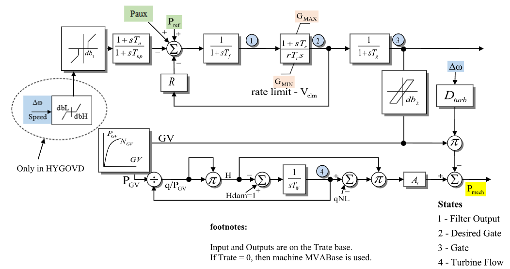
Figure 1: HYGOV governor model. Figure courtesy of the PowerWorld HYGOV model reference.
Model Parameters
Symbol |
Units |
JSON |
Description |
Typical Value |
Note |
|---|---|---|---|---|---|
\(T^\mathrm{rate}\) |
[MW] |
|
Turbine-rating power base |
100.0 |
Required |
\(R_{\mathrm{perm}}\) |
[p.u.] |
|
Permanent droop |
0.04 |
Source label: |
\(R_{\mathrm{temp}}\) |
[p.u.] |
|
Temporary droop |
0.3 |
Source label: |
\(T_\mathrm{r}\) |
[s] |
|
Temporary-droop reset time constant |
5.0 |
|
\(T_\mathrm{f}\) |
[s] |
|
Governor error filter time constant |
0.05 |
|
\(T_\mathrm{g}\) |
[s] |
|
Gate servo time constant |
0.5 |
|
\(V_{\mathrm{elm}}\) |
[p.u./s] |
|
Maximum desired-gate velocity magnitude |
0.2 |
|
\(G^{\max}\) |
[p.u.] |
|
Configured upper gate response limit |
1.0 |
|
\(G^{\min}\) |
[p.u.] |
|
Configured lower gate response limit |
0.0 |
|
\(T_\mathrm{w}\) |
[s] |
|
Water inertia time constant |
1.0 |
|
\(A_\mathrm{t}\) |
[p.u.] |
|
Turbine gain |
1.2 |
|
\(D_{\mathrm{turb}}\) |
[p.u.] |
|
Turbine damping coefficient |
0.5 |
|
\(q_{\mathrm{NL}}\) |
[p.u.] |
|
No-load flow at nominal head |
0.05 |
|
\(T_\mathrm{n}\) |
[s] |
|
Speed lead–lag numerator time constant |
0.0 |
|
\(T_{\mathrm{np}}\) |
[s] |
|
Speed lead–lag denominator time constant |
0.0 |
|
\(D_{\omega}\) |
[p.u.] |
|
Type 1 speed deadband threshold |
0.0 |
|
\(D_2\) |
[p.u.] |
|
Unsupported mechanical backlash deadband |
0.0 |
Nonzero values warn and are ignored |
\(H_{\mathrm{dam}}\) |
[p.u.] |
|
Configured dam head |
1.0 |
Lower bound on effective head |
\(G_V^{(k)}\) |
[p.u.] |
|
Gate point \(k\) of the gain curve |
0.0 |
\(k=0,\ldots,5\) |
\(P_{\mathrm{GV}}^{(k)}\) |
[p.u.] |
|
Power point \(k\) of the gain curve |
0.0 |
\(k=0,\ldots,5\) |
Real-valued parameters accept real or integer JSON values. All-zero Gv and
Pgv source points select the identity curve.
Parameter Validation
A valid HYGOV parameter set must satisfy the following conditions:
Real-valued parameters, Known initial values, power bases, and base-conversion
ratios must be finite. The bases and ratios must also be positive.
The final condition uses the steady mechanical power and tolerance defined under Internal Initialization.
Model Derived Parameters
Let \(\epsilon_T=10^{-3}\ \mathrm{s}\). A time constant below \(\epsilon_T\) is raised to that floor in place, so every equation below uses the raised value:
Multiplying by \(k_\mathrm{base}\) converts system base to component base; \(S^\mathrm{sys}\) is the system power base in VA.
Model Ports
Name |
Port |
Init |
Description |
|---|---|---|---|
|
Input |
Known |
Machine speed deviation |
|
Input |
Unknown |
Active-power/load reference |
|
Input |
Known |
Auxiliary power input |
|
Output |
Known |
Mechanical power output |
Known values are seeded before initialization and preserved. Unknown inputs
are initialized in attached signal storage or held constant when unattached. The
pmech output must be assigned. The signal inputs are optional. Unattached
speed and paux inputs default to zero.
Model Variables
Internal Variables
Differential
Symbol |
Units |
Description |
Note |
|---|---|---|---|
\(x_\mathrm{n}\) |
[p.u.] |
Speed lead–lag denominator state |
Not circled in Fig. 1. Realizes the |
\(x_\mathrm{f}\) |
[p.u.] |
Governor error filter output |
State 1 in Fig. 1 |
\(c\) |
[p.u.] |
Desired-gate position |
State 2 in Fig. 1 |
\(g\) |
[p.u.] |
Gate position |
State 3 in Fig. 1 |
\(q\) |
[p.u.] |
Turbine flow |
State 4 in Fig. 1 |
Algebraic
Symbol |
Units |
Description |
Note |
|---|---|---|---|
\(\omega_{\mathrm{db}}\) |
[p.u.] |
Type 1 deadbanded speed deviation |
|
\(e_f\) |
[p.u.] |
Governor error into the filter |
Reference path less conditioned speed and permanent-droop feedback |
\(f_c\) |
[p.u./s] |
Desired-gate derivative target |
Before rate and position limits |
\(r_c\) |
[p.u./s] |
Rate-limited desired-gate derivative target |
Limited by \(\pm V_{\mathrm{elm}}\) |
\(P_{\mathrm{GV}}\) |
[p.u.] |
Nonlinear gate-to-power curve output |
\(N_{\mathrm{GV}}(g)\) |
\(H\) |
[p.u.] |
Turbine head |
Implicit water-column head |
\(P_\mathrm{m}\) |
[p.u.] |
Mechanical power to generator |
System base |
External Variables
Differential
None.
Algebraic
Symbol |
Units |
Description |
Note |
|---|---|---|---|
\(\omega\) |
[p.u.] |
Machine speed deviation |
Optional signal port |
\(P^\mathrm{ref}\) |
[p.u.] |
Active-power/load reference |
Optional signal port |
\(P^\mathrm{aux}\) |
[p.u.] |
Auxiliary power input |
Optional signal port |
Model Equations
Smooth functions: antiwindup, clamp, deadband1, linseg.
Internal Equations
Differential
The effective desired-gate response limits \(G_{\mathrm{resp}}^{\min}\) and \(G_{\mathrm{resp}}^{\max}\) and the effective dam head \(H_{\mathrm{dam}}^{\mathrm{eff}}\) are resolved during initialization.
Algebraic
External Equations
None.
Initialization
Input Initialization
Initialization never replaces the system-base value held in \(P_\mathrm{m}\).
Internal Initialization
Initialization requires an exactly zero speed deviation, \(\omega = 0\). Restart initialization of a moving machine is not supported. All internal derivatives are set to zero.
Initialization first solves the gate at the configured dam head over the full
\([G_V^{(0)},G_V^{(5)}]\) gate curve. If that gate lies outside the configured
\([G^{\min},G^{\max}]\) interval, the corresponding response limit is expanded
to include it. The configured parameters are unchanged. This matches
PowerWorld’s default Modify Limits and Run treatment of initial limit
violations.
If the required mechanical power exceeds the value at \(G_V^{(5)}\), the gate is pinned there and an effective dam head \(H_{\mathrm{dam}}^{\mathrm{eff}} \ge H_{\mathrm{dam}}\) is raised to reproduce the operating point. Both searches use the same smooth \(N_{\mathrm{GV}}\) curve as the residual. No upper limit is applied to the head adjustment. The effective values remain the response limits and water-column setpoint during simulation.
A value within \(\epsilon_{\mathrm{init}} = 100\,\epsilon_{\mathrm{mach}}\) below the \(G_V^{(0)}\) endpoint initializes at \(G_V^{(0)}\) with a mechanical-power residual up to \(\epsilon_{\mathrm{init}}\). A lower value, or a high-side value without a finite effective dam head, is rejected. All other accepted values initialize with every residual at machine rounding.
Every check resolves before state, the effective response limits, the effective dam head, or signals are written, so a rejected initialization leaves them unchanged.
Output Initialization
Monitors
Monitor |
Units |
Description |
Note |
|---|---|---|---|
|
[p.u.] |
Mechanical-power output |
\(P_\mathrm{m}\) (system base) |
|
[p.u.] |
Governor error filter output |
\(x_\mathrm{f}\) (component base) |
|
[p.u.] |
Desired-gate position |
\(c\) (component base) |
|
[p.u.] |
Gate position |
\(g\) (component base) |
|
[p.u.] |
Turbine flow |
\(q\) (component base) |
|
[p.u.] |
Turbine head |
\(H\) (component base) |
Appendix A: Backlash
Input \(u\), output \(y\), half-play \(b\), with \(|u - y| \le b\).
which can be written in terms of our smooth functions as
CommonMath defines the ramp,
above, and
below targets and smooth approximations. This is deferred until we permit non Hessenberg forms. Once permitted we should define: