REECA
REECA is a WECC renewable energy electrical control model for inverter-coupled resources. In GridKit it is represented as a signal-control model that computes active- and reactive-current commands.
Warning
Post-dip reactive-current injection and active-current limit holds require timer/history states that are not modeled. \(T_{\mathrm{hld}}\) and \(T_{\mathrm{hld2}}\) must be zero: \(I_{\mathrm{qinj}}^{\mathrm{frz}}\) is unused, and \(I_{\mathrm{p}}^{\max}\) is recalculated from VDL2 and current-circle logic at each residual evaluation instead of held after voltage recovery.
Notes
Internal electrical quantities and current commands are on model base unless otherwise stated.
Optional signal inputs default to their documented constant values when omitted.
Block Diagram
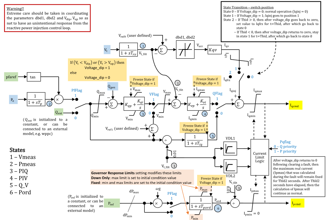
Figure 1: REECA block diagram. Figure courtesy of PowerWorld
Model Parameters
Symbol |
Units |
JSON |
Description |
Typical Value |
Note |
|---|---|---|---|---|---|
\(S^{\mathrm{base}}\) |
[MVA] |
TBD |
REECA model power base |
TBD |
Source label: |
\(s_{\mathrm{pf}}\) |
[binary] |
TBD |
Power-factor control flag |
TBD |
Source label: |
\(s_V\) |
[binary] |
TBD |
Voltage-control mode flag |
TBD |
Source label: |
\(s_Q\) |
[binary] |
TBD |
Reactive-power control flag |
TBD |
Source label: |
\(s_P\) |
[binary] |
TBD |
Active-power reference speed-multiplier flag |
TBD |
Source label: |
\(s_\mathrm{PQ}\) |
[binary] |
TBD |
P/Q priority flag for converter current limit |
TBD |
Source label: |
\(T_{\mathrm{rv}}\) |
[s] |
TBD |
Voltage-measurement filter time constant |
TBD |
Source label: |
\(T_{\mathrm{p}}\) |
[s] |
TBD |
Electrical-power measurement filter time constant |
TBD |
Source label: |
\(V_{\mathrm{ref0}}\) |
[p.u.] |
TBD |
Outer-loop voltage reference |
TBD |
Source label: |
\(V_{\mathrm{dip}}\) |
[p.u.] |
TBD |
Low-voltage threshold for reactive-current injection logic |
TBD |
Source label: |
\(V_{\mathrm{up}}\) |
[p.u.] |
TBD |
High-voltage threshold for reactive-current injection logic |
TBD |
Source label: |
\(D_{\mathrm{bd1}}\) |
[p.u.] |
TBD |
Overvoltage deadband for voltage-error response |
TBD |
Source label: |
\(D_{\mathrm{bd2}}\) |
[p.u.] |
TBD |
Undervoltage deadband for voltage-error response |
TBD |
Source label: |
\(K_{\mathrm{qv}}\) |
[p.u.] |
TBD |
Reactive-current injection gain during voltage dip/overvoltage logic |
TBD |
Source label: |
\(I_{\mathrm{qinj}}^{\min}\) |
[p.u.] |
TBD |
Minimum reactive-current injection limit |
TBD |
Source label: |
\(I_{\mathrm{qinj}}^{\max}\) |
[p.u.] |
TBD |
Maximum reactive-current injection limit |
TBD |
Source label: |
\(I_{\mathrm{qinj}}^{\mathrm{frz}}\) |
[p.u.] |
TBD |
Held reactive-current injection value after voltage dip |
TBD |
Source label: |
\(T_{\mathrm{hld}}\) |
[s] |
TBD |
Reactive-current injection hold time after voltage dip clears |
TBD |
Source label: |
\(Q^{\max}\) |
[p.u.] |
TBD |
Maximum reactive-power control limit |
TBD |
Source label: |
\(Q^{\min}\) |
[p.u.] |
TBD |
Minimum reactive-power control limit |
TBD |
Source label: |
\(K_{\mathrm{qp}}\) |
[p.u.] |
TBD |
Reactive-power control proportional gain |
TBD |
Source label: |
\(K_{\mathrm{qi}}\) |
[p.u./s] |
TBD |
Reactive-power control integral gain |
TBD |
Source label: |
\(V^{\max}\) |
[p.u.] |
TBD |
Maximum voltage-control limit |
TBD |
Source label: |
\(V^{\min}\) |
[p.u.] |
TBD |
Minimum voltage-control limit |
TBD |
Source label: |
\(V_{\mathrm{ref1}}\) |
[p.u.] |
TBD |
Inner-loop voltage-control reference/bias |
0 |
Source label: |
\(K_{\mathrm{vp}}\) |
[p.u.] |
TBD |
Voltage-control proportional gain |
TBD |
Source label: |
\(K_{\mathrm{vi}}\) |
[p.u./s] |
TBD |
Voltage-control integral gain |
TBD |
Source label: |
\(T_{\mathrm{iq}}\) |
[s] |
TBD |
Reactive-current command lag time constant |
TBD |
Source label: |
\(T_{\mathrm{pord}}\) |
[s] |
TBD |
Active-power order filter time constant |
TBD |
Source label: |
\(R_P^{\max}\) |
[p.u./s] |
TBD |
Positive active-power order ramp-rate limit |
TBD |
Source label: |
\(R_P^{\min}\) |
[p.u./s] |
TBD |
Negative active-power order ramp-rate limit |
TBD |
Source label: |
\(P^{\max}\) |
[p.u.] |
TBD |
Maximum active-power order limit |
TBD |
Source label: |
\(P^{\min}\) |
[p.u.] |
TBD |
Minimum active-power order limit |
TBD |
Source label: |
\(I^{\max}\) |
[p.u.] |
TBD |
Maximum total converter current |
TBD |
Source label: |
\(V_{\mathrm{q},1}\) |
[p.u.] |
TBD |
VDL1 voltage point 1 |
TBD |
Source label: |
\(I_{\mathrm{q},1}^{\max}\) |
[p.u.] |
TBD |
VDL1 reactive-current limit point 1 |
TBD |
Source label: |
\(V_{\mathrm{q},2}\) |
[p.u.] |
TBD |
VDL1 voltage point 2 |
TBD |
Source label: |
\(I_{\mathrm{q},2}^{\max}\) |
[p.u.] |
TBD |
VDL1 reactive-current limit point 2 |
TBD |
Source label: |
\(V_{\mathrm{q},3}\) |
[p.u.] |
TBD |
VDL1 voltage point 3 |
TBD |
Source label: |
\(I_{\mathrm{q},3}^{\max}\) |
[p.u.] |
TBD |
VDL1 reactive-current limit point 3 |
TBD |
Source label: |
\(V_{\mathrm{q},4}\) |
[p.u.] |
TBD |
VDL1 voltage point 4 |
TBD |
Source label: |
\(I_{\mathrm{q},4}^{\max}\) |
[p.u.] |
TBD |
VDL1 reactive-current limit point 4 |
TBD |
Source label: |
\(V_{\mathrm{p},1}\) |
[p.u.] |
TBD |
VDL2 voltage point 1 |
TBD |
Source label: |
\(I_{\mathrm{p},1}^{\max}\) |
[p.u.] |
TBD |
VDL2 active-current limit point 1 |
TBD |
Source label: |
\(V_{\mathrm{p},2}\) |
[p.u.] |
TBD |
VDL2 voltage point 2 |
TBD |
Source label: |
\(I_{\mathrm{p},2}^{\max}\) |
[p.u.] |
TBD |
VDL2 active-current limit point 2 |
TBD |
Source label: |
\(V_{\mathrm{p},3}\) |
[p.u.] |
TBD |
VDL2 voltage point 3 |
TBD |
Source label: |
\(I_{\mathrm{p},3}^{\max}\) |
[p.u.] |
TBD |
VDL2 active-current limit point 3 |
TBD |
Source label: |
\(V_{\mathrm{p},4}\) |
[p.u.] |
TBD |
VDL2 voltage point 4 |
TBD |
Source label: |
\(I_{\mathrm{p},4}^{\max}\) |
[p.u.] |
TBD |
VDL2 active-current limit point 4 |
TBD |
Source label: |
\(T_{\mathrm{hld2}}\) |
[s] |
TBD |
Active-current limit hold time after voltage dip clears |
TBD |
Source label: |
JSON parameter names are not yet specified.
Parameter Validation
A valid REECA parameter set must satisfy the following conditions:
Model Derived Parameters
The off-mode flag complements are:
The VDL functions use GridKit’s smooth Linear Segment helper and provide flat extrapolation outside the first and fourth voltage points:
Model Ports
Name |
Port |
Init |
Description |
|---|---|---|---|
|
Bus |
TBD |
Terminal-bus voltage |
|
Input |
TBD |
Generator speed deviation |
|
Input |
TBD |
Electrical active-power feedback |
|
Input |
TBD |
Reactive-power feedback |
|
Input |
TBD |
External reactive-power command |
|
Input |
TBD |
Power-factor angle reference |
|
Input |
TBD |
Active-power reference |
|
Output |
TBD |
Reactive-current command |
|
Output |
TBD |
Active-current command |
Model Variables
Internal Variables
Differential
Symbol |
Units |
Description |
Note |
|---|---|---|---|
\(V_{\mathrm{meas}}\) |
[p.u.] |
Filtered terminal voltage |
State 1 in Fig. 1; Source label: |
\(P_{\mathrm{meas}}\) |
[p.u.] |
Filtered electrical power |
State 2 in Fig. 1; Source label: |
\(x_{\mathrm{PIQ}}\) |
[p.u.] |
Reactive-power PI controller state |
State 3 in Fig. 1; Source label: |
\(x_{\mathrm{PIV}}\) |
[p.u.] |
Voltage PI controller state |
State 4 in Fig. 1; Source label: |
\(Q_V\) |
[p.u.] |
Reactive-current command lag state |
State 5 in Fig. 1; Source label: |
\(P_{\mathrm{ord}}\) |
[p.u.] |
Filtered active-power order |
State 6 in Fig. 1; Source label: |
Algebraic
Symbol |
Units |
Description |
Note |
|---|---|---|---|
\(V_T\) |
[p.u.] |
Terminal voltage magnitude |
|
\(V_{\mathrm{meas}}^{\mathrm{safe}}\) |
[p.u.] |
Safe filtered terminal voltage for divider blocks |
Lower bounded by 0.01 |
\(s_{\mathrm{dip}}\) |
[binary] |
Voltage-dip/overvoltage freeze indicator |
1 when outside voltage thresholds |
\(V_{\mathrm{err}}\) |
[p.u.] |
Deadbanded voltage error |
Defined by CommonMath |
\(I_{\mathrm{qv}}\) |
[p.u.] |
Reactive-current injection candidate |
Converter base |
\(Q_{\mathrm{ref}}\) |
[p.u.] |
Selected reactive-power reference |
From power-factor or external reactive-power command |
\(e_Q\) |
[p.u.] |
Reactive-power control error |
Limited \(Q_{\mathrm{ref}}\) minus \(Q_{\mathrm{gen}}\) |
\(V_{\mathrm{PIQ}}\) |
[p.u.] |
Reactive-power control PI output |
Limited by \(V^{\min}\) and \(V^{\max}\) |
\(e_{\mathrm{PIV}}\) |
[p.u.] |
Voltage-control PI error |
Selected voltage-control signal minus \(V_{\mathrm{meas}}\) |
\(f_{\mathrm{pord}}\) |
[p.u./s] |
Active-power order derivative before ramp-rate limiting |
Feeds \(r_{\mathrm{pord}}\) |
\(r_{\mathrm{pord}}\) |
[p.u./s] |
Ramp-rate-limited active-power order derivative |
Feeds \(P_{\mathrm{ord}}\) anti-windup |
\(I_{\mathrm{q}}^{\mathrm{circ}}\) |
[p.u.] |
Reactive-current limit from converter current circle |
Converter base; nonnegative algebraic branch |
\(I_{\mathrm{p}}^{\mathrm{circ}}\) |
[p.u.] |
Active-current limit from converter current circle |
Converter base; nonnegative algebraic branch |
\(I_{\mathrm{q}}^{\max}\) |
[p.u.] |
Final reactive-current upper limit |
Converter base; updated by VDL1 and current-limit logic |
\(I_{\mathrm{p}}^{\max}\) |
[p.u.] |
Final active-current upper limit |
Converter base; updated by VDL2 and current-limit logic |
\(I_{\mathrm{qbase}}\) |
[p.u.] |
Base reactive-current command |
Converter base; before \(s_Q\) selection and reactive-current injection |
\(I_{\mathrm{q}}^{\mathrm{raw}}\) |
[p.u.] |
Raw reactive-current command before final limit |
Converter base |
\(I_{\mathrm{q}}^{\mathrm{cmd}}\) |
[p.u.] |
Reactive-current command output |
Converter base |
\(I_{\mathrm{p}}^{\mathrm{cmd}}\) |
[p.u.] |
Active-current command output |
Converter base |
External Variables
Differential
Symbol |
Units |
Description |
Note |
|---|---|---|---|
\(\omega\) |
[p.u.] |
Generator speed deviation |
Optional, defaults to zero; source diagram \(\omega_\mathrm{g} = 1 + \omega\) |
Algebraic
Symbol |
Units |
Description |
Note |
|---|---|---|---|
\(V_r\) |
[p.u.] |
Terminal voltage, real component |
Owned by bus object |
\(V_i\) |
[p.u.] |
Terminal voltage, imaginary component |
Owned by bus object |
\(P_\mathrm{e}\) |
[p.u.] |
Electrical active power |
Source label: |
\(Q_{\mathrm{gen}}\) |
[p.u.] |
Reactive-power feedback |
Source label: |
\(Q_{\mathrm{ext}}\) |
[p.u.] |
External reactive-power command |
Optional, defaults to initialized constant |
\(\phi_{\mathrm{pf}}^{\mathrm{ref}}\) |
[rad] |
Power-factor angle reference |
Source label: |
\(P_{\mathrm{ref}}\) |
[p.u.] |
External active-power reference |
Optional, defaults to initialized constant |
Model Equations
Smooth functions: antiwindup, clamp, deadband2, max, min, outside.
For readability, define:
Internal Equations
Differential
Algebraic
The \(V_T\), \(I_{\mathrm{q}}^{\mathrm{circ}}\), and \(I_{\mathrm{p}}^{\mathrm{circ}}\) variables use nonnegative branches of squared algebraic residuals.
External Equations
None.
Initialization
All internal derivatives initialize to zero. Omitted optional signals use the following constants:
Connected optional signals use their supplied initial values; if only some are omitted, compute the omitted constants with the connected initial values. Inconsistent supplied commands require a residual solve or initialization rejection.
If \(V_{\mathrm{ref0}}\) is omitted, set \(V_{\mathrm{ref0}}\leftarrow V_T\).
Then evaluate the upstream algebraic chain:
The PI states must satisfy:
An unsaturated start requires \(e_Q=0\) and \(e_{\mathrm{PIV}}=0\). When \(s_V=1\), set \(V_{\mathrm{PIQ}}\leftarrow V_{\mathrm{meas}}\); when \(s_V=0\), the supplied \(Q_{\mathrm{ref}}+V_{\mathrm{ref1}}\) must equal \(V_{\mathrm{meas}}\). Then \(x_{\mathrm{PIQ}}\leftarrow V_{\mathrm{PIQ}}-K_{\mathrm{qp}}e_Q\). Saturated starts require a solve against the anti-windup residuals.
Finish by evaluating \(g_q(V_{\mathrm{meas}})\), \(g_p(V_{\mathrm{meas}})\), and the current-limit and current-command algebraic residuals in priority order. At the command steps, use the power-flow current targets before final limiting:
Evaluate current limits and commands in this order:
\(s_\mathrm{PQ}=0\): \(I_{\mathrm{q}}^{\mathrm{circ}}\), \(I_{\mathrm{q}}^{\max}\), \(I_{\mathrm{qbase}}\), \(I_{\mathrm{q}}^{\mathrm{raw}}\), \(I_{\mathrm{q}}^{\mathrm{cmd}}\), \(I_{\mathrm{p}}^{\mathrm{circ}}\), \(I_{\mathrm{p}}^{\max}\), \(I_{\mathrm{p}}^{\mathrm{cmd}}\).
\(s_\mathrm{PQ}=1\): \(I_{\mathrm{p}}^{\mathrm{circ}}\), \(I_{\mathrm{p}}^{\max}\), \(I_{\mathrm{p}}^{\mathrm{cmd}}\), \(I_{\mathrm{q}}^{\mathrm{circ}}\), \(I_{\mathrm{q}}^{\max}\), \(I_{\mathrm{qbase}}\), \(I_{\mathrm{q}}^{\mathrm{raw}}\), \(I_{\mathrm{q}}^{\mathrm{cmd}}\).
After \(I_{\mathrm{q}}^{\max}\) and \(I_{\mathrm{qbase}}\) are known, initialize the voltage PI state:
The current-circle variables use the nonnegative branch of the squared algebraic residuals; initialization must reject negative radicands. A standard steady-state initialization assumes \(s_{\mathrm{dip}}=0\). If initialized during voltage-dip or overvoltage logic, \(Q_V\), \(P_{\mathrm{ord}}\), and the PI histories are not uniquely determined without the unsupported hold-timer histories, so the implementation should solve a saturation-consistent state or reject the start.
Monitors
Monitor |
Units |
Description |
Note |
|---|---|---|---|
|
[p.u.] |
Reactive-current command output |
Converter base |
|
[p.u.] |
Active-current command output |
Converter base |
|
[p.u.] |
Filtered terminal voltage |
|
|
[p.u.] |
Filtered electrical power |
|
|
[p.u.] |
Reactive-power PI controller state |
|
|
[p.u.] |
Voltage PI controller state |
|
|
[p.u.] |
Reactive-current command lag state |
|
|
[p.u.] |
Filtered active-power order |
|
|
[p.u.] |
Selected reactive-power reference |
|
|
[binary] |
Voltage-dip/overvoltage freeze indicator |
|
|
[p.u.] |
Final reactive-current upper limit |
Converter base |
|
[p.u.] |
Final active-current upper limit |
Converter base |
|
[p.u.] |
Reactive-current injection candidate |
Converter base |
|
[p.u.] |
Reactive-power control PI output |
|
|
[p.u.] |
Base reactive-current command |
Converter base |