REECB
REECB is a WECC renewable electrical-control model with power-factor, reactive-power, voltage, and active-power command paths for an inverter-coupled resource.[1]
Warning
GridKit does not inherit mva from the associated REGCA model. Set mva
to the REGCA component base.[2]
Warning
GridKit does not yet apply the associated generator’s Governor Response Limits
modes Down Only and Fixed to REECB.
Notes
In direct-voltage mode (\(s_Q=1\), \(s_V=0\))
qextcarries a terminal-voltage reference instead of a system-base reactive power.
Block Diagram
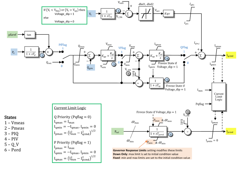
Figure 1: REECB electrical-control model. Figure courtesy of the PowerWorld REEC_B model reference.
Model Parameters
Symbol |
Units |
JSON |
Description |
Typical Value |
Note |
|---|---|---|---|---|---|
\(S^\mathrm{base}\) |
[MVA] |
|
REECB component power base |
Required |
Must be positive |
\(s_\mathrm{pf}\) |
[boolean] |
|
Power-factor control selector |
|
|
\(s_V\) |
[boolean] |
|
Voltage-reference selector under \(s_Q=1\) |
|
|
\(s_Q\) |
[boolean] |
|
Reactive-path selector |
|
|
\(s_\mathrm{pq}\) |
[boolean] |
|
Converter current-priority selector |
|
|
\(T_\mathrm{rv}\) |
[s] |
|
Voltage-measurement filter time constant |
0.02 |
State 1 in Fig. 1 |
\(T_\mathrm{p}\) |
[s] |
|
Electrical-power measurement filter time constant |
0.0 |
State 2 in Fig. 1 |
\(V^\mathrm{ref}\) |
[p.u.] |
|
Reactive-current-injection voltage reference |
\(V_T\) |
Initialized from terminal voltage when omitted |
\(V_\mathrm{dip}\) |
[p.u.] |
|
Low-voltage threshold for the voltage-band gate |
0.85 |
|
\(V_\mathrm{up}\) |
[p.u.] |
|
High-voltage threshold for the voltage-band gate |
1.15 |
|
\(D_1^\mathrm{db}\) |
[p.u.] |
|
Lower deadband threshold for voltage-error response |
0.0 |
|
\(D_2^\mathrm{db}\) |
[p.u.] |
|
Upper deadband threshold for voltage-error response |
0.0 |
|
\(K_\mathrm{qv}\) |
[p.u.] |
|
Reactive-current injection gain |
5.0 |
|
\(I_{q,\mathrm{inj}}^{\min}\) |
[p.u.] |
|
Minimum reactive-current injection |
-1.1 |
|
\(I_{q,\mathrm{inj}}^{\max}\) |
[p.u.] |
|
Maximum reactive-current injection |
1.1 |
|
\(Q^{\max}\) |
[p.u.] |
|
Maximum reactive-power control output |
0.436 |
|
\(Q^{\min}\) |
[p.u.] |
|
Minimum reactive-power control output |
-0.436 |
|
\(K_\mathrm{qp}\) |
[p.u.] |
|
Reactive-power controller proportional gain |
0.0 |
|
\(K_\mathrm{qi}\) |
[p.u./s] |
|
Reactive-power controller integral gain |
0.1 |
|
\(V^{\max}\) |
[p.u.] |
|
Maximum voltage-control output |
1.1 |
|
\(V^{\min}\) |
[p.u.] |
|
Minimum voltage-control output |
0.9 |
|
\(K_\mathrm{vp}\) |
[p.u.] |
|
Voltage controller proportional gain |
18.0 |
|
\(K_\mathrm{vi}\) |
[p.u./s] |
|
Voltage controller integral gain |
5.0 |
|
\(T_\mathrm{iq}\) |
[s] |
|
Reactive-current command lag time constant |
0.02 |
State 5 in Fig. 1 |
\(T_\mathrm{pord}\) |
[s] |
|
Active-power order filter time constant |
0.02 |
State 6 in Fig. 1 |
\(R_P^{\max}\) |
[p.u./s] |
|
Positive active-power order ramp-rate limit |
99.0 |
|
\(R_P^{\min}\) |
[p.u./s] |
|
Negative active-power order ramp-rate limit |
-99.0 |
|
\(P^{\max}\) |
[p.u.] |
|
Maximum active-power order |
1.0 |
|
\(P^{\min}\) |
[p.u.] |
|
Minimum active-power order |
0.0 |
|
\(I^{\max}\) |
[p.u.] |
|
Maximum converter current |
1.3 |
Real-valued parameters accept real or integer JSON values; selectors require Boolean JSON values.
Parameter Validation
A valid REECB parameter set must satisfy the following conditions:
Enabling both PfFlag and QFlag logs an atypical-configuration warning.
Model Derived Parameters
Let \(\epsilon_T=10^{-3}\ \mathrm{s}\). A time constant below \(\epsilon_T\) is raised to that floor in place, so every equation below uses the raised value:
Multiplying by \(k_\mathrm{base}\) converts system base to component base.
Model Ports
Name |
Port |
Init |
Description |
|---|---|---|---|
|
Bus |
Known |
Terminal-bus voltage |
|
Input |
Known |
Active-power feedback |
|
Input |
Known |
Reactive-power feedback |
|
Input |
Unknown |
Volt/VAr reference |
|
Input |
Unknown |
Power-factor angle reference |
|
Input |
Unknown |
Active-power reference |
|
Output |
Known |
Reactive-current command |
|
Output |
Known |
Active-current command |
bus is required; signal ports are optional and must be linked when attached.
Known values are seeded before initialization and preserved. Unknown inputs
are initialized in attached signal storage or held constant when unattached.
Model Variables
Internal Variables
Differential
Symbol |
Units |
Description |
Note |
|---|---|---|---|
\(V^\mathrm{meas}\) |
[p.u.] |
Filtered terminal voltage |
State 1 in Fig. 1; Source label: |
\(P^\mathrm{meas}\) |
[p.u.] |
Filtered electrical power |
State 2 in Fig. 1; Source label: |
\(x_Q^\mathrm{PI}\) |
[p.u.] |
Reactive-power PI controller state |
State 3 in Fig. 1; Source label: |
\(x_V^\mathrm{PI}\) |
[p.u.] |
Voltage-control PI controller state |
State 4 in Fig. 1; Source label: |
\(Q_V\) |
[p.u.] |
Reactive-current command lag state |
State 5 in Fig. 1; Source label: |
\(P^\mathrm{ord}\) |
[p.u.] |
Filtered active-power order |
State 6 in Fig. 1; Source label: |
Algebraic
Symbol |
Units |
Description |
Note |
|---|---|---|---|
\(V_T\) |
[p.u.] |
Terminal voltage magnitude |
|
\(V_\mathrm{safe}^\mathrm{meas}\) |
[p.u.] |
Safe measured voltage |
|
\(s_\mathrm{dip}\) |
[-] |
Voltage-band gate |
|
\(I_q^\mathrm{inj}\) |
[p.u.] |
Reactive-current injection |
Component base |
\(Q^\mathrm{ref}\) |
[p.u.] |
Reactive-power reference |
Component base |
\(e_Q\) |
[p.u.] |
Reactive-power error |
Component base |
\(V_Q^\mathrm{PI}\) |
[p.u.] |
Reactive-power PI output |
|
\(e_V^\mathrm{PI}\) |
[p.u.] |
Voltage-control error |
|
\(r_P^\mathrm{ord}\) |
[p.u./s] |
Limited active-power order rate |
Component base |
\(I_L^\mathrm{cap}\) |
[p.u.] |
Off-axis current capacity |
Component base |
\(I_q^{\max}\) |
[p.u.] |
Reactive-current limit |
Component base |
\(I_p^{\max}\) |
[p.u.] |
Active-current limit |
Component base |
\(I_q^\mathrm{base}\) |
[p.u.] |
Voltage-controller current |
Component base |
\(I_q^\mathrm{raw}\) |
[p.u.] |
Pre-limit reactive-current command |
Component base |
\(I_q^\mathrm{cmd}\) |
[p.u.] |
Reactive-current command output |
System base |
\(I_p^\mathrm{cmd}\) |
[p.u.] |
Active-current command output |
System base |
External Variables
Differential
None.
Algebraic
Symbol |
Units |
Description |
Note |
|---|---|---|---|
\(V_r\) |
[p.u.] |
Terminal voltage, real component |
Bus input |
\(V_i\) |
[p.u.] |
Terminal voltage, imaginary component |
Bus input |
\(P_\mathrm{e}\) |
[p.u.] |
Electrical active-power feedback |
Optional signal port |
\(Q^\mathrm{gen}\) |
[p.u.] |
Reactive-power feedback |
Optional signal port |
\(Q^\mathrm{ext}\) |
[p.u.] |
External Volt/VAr reference |
Optional signal port |
\(\phi^\mathrm{ref}\) |
[rad] |
Power-factor angle reference |
Optional signal port |
\(P^\mathrm{ref}\) |
[p.u.] |
External active-power reference |
Optional signal port |
Model Equations
Smooth functions: antiwindup, clamp, deadband2, inside, max.
Internal Equations
Differential
Algebraic
Here
\(I^\mathrm{high}=s_\mathrm{pq}k_\mathrm{base}I_p^\mathrm{cmd}
+s_\mathrm{pq}^\mathrm{off}k_\mathrm{base}I_q^\mathrm{cmd}\) and
\(\epsilon_\mathrm{init}=100\epsilon_\mathrm{machine}\).
Appendix B defines sqrtramp.
Appendix A defines aslew.
External Equations
None.
Initialization
REECB reconstructs a steady operating point. Arbitrary-state restart is unsupported.
Input Initialization
Internal Initialization
Initialization resolves the steady-state quantities in dependency order; all
internal derivatives start at zero. Initialize the component-base commands:
\(I_p\leftarrow k_\mathrm{base}I_p^\mathrm{cmd}\) and
\(I_q\leftarrow k_\mathrm{base}I_q^\mathrm{cmd}\).
REECB’s iclamp helper inverts the smooth CommonMath
clamp during initialization.
At a bound, REECB uses an outward offset
\(\delta=-\ln(\text{expm1}(\mu\epsilon_\mathrm{init}/2))/\mu\) to keep the clamp error
within \(\epsilon_\mathrm{init}\); collapsed bounds return the bound.
Let \(I_q^\mathrm{need}\) be the smooth-clamp input magnitude required to reproduce \(I_q\), including the Volt/VAr recovery margin. Initialization raises \(I^{\max}\), if needed, to a finite limit satisfying
The solution initializes
\(I^{\max}\leftarrow I\) and
\(I_L^\mathrm{cap}\leftarrow\text{sqrtramp}\big((I-h)(I+h)\big)\). The
operating point is rejected if no finite solution exists or the
reactive-current injection is incompatible. Q, V, and P limits are expanded as
needed; each adjustment logs a warning. This matches PowerWorld’s default
Modify Limits and Run treatment of initial limit violations.
This preserves the supplied operating point for steady-state initialization;
subsequent simulation uses the adjusted limits.
The references resolved under Output Initialization give
Invalid or non-equilibrium operating points are rejected before any state, limit, latch, or signal is changed.
Output Initialization
REECB writes the resolved references to attached signal inputs; unattached ports retain them as constant inputs.
Monitors
Monitor |
Units |
Description |
Note |
|---|---|---|---|
|
[p.u.] |
Reactive-current command output |
\(I_q^\mathrm{cmd}\) (system base) |
|
[p.u.] |
Active-current command output |
\(I_p^\mathrm{cmd}\) (system base) |
|
[p.u.] |
Filtered terminal voltage |
\(V^\mathrm{meas}\) |
|
[p.u.] |
Filtered electrical power |
\(P^\mathrm{meas}\) (component base) |
Appendix A: aslew
For \(\ell<0<u\), REECB uses
where \(\rho\) is GridKit’s smooth
ramp. With exact one-sided ramps this
reduces to \(\text{clamp}(f;\ell,u)\); the smooth form preserves
\(\text{aslew}(0;\ell,u)=0\).
Appendix B: sqrtramp
The off-axis capacity approaches \(\sqrt{\max(0,s)}\), where \(s=(I^{\max}-I^\mathrm{high})(I^{\max}+I^\mathrm{high})\). Let \(\kappa=\epsilon_\mathrm{init}/\mu\), with \(\mu\) GridKit’s smoothing scale. REECB uses
Both softenings are differentiable for every finite \(s\). The narrow hinge leaves a negligible positive capacity when the circle is closed or over-driven, while preserving the current-command dependence through the transition. Increasing \(\mu\) recovers the exact current-circle leg.