Bus
A bus owns the terminal voltage components \(V_r\) and \(V_i\) and the current-balance residuals. Each connected device adds its current injection after the bus resets the residuals to zero.
Notes
Current entering the bus has positive sign, and current exiting the bus has negative sign.
Block Diagram
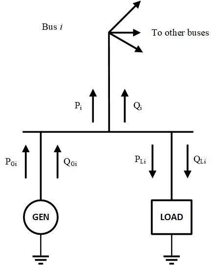
Figure 1: Bus-variable diagram. This should be updated to represent current balance instead of power balance.
Model Parameters
Symbol |
Units |
JSON |
Description |
Typical Value |
Note |
|---|---|---|---|---|---|
\(V_\mathrm{base}\) |
[kV] |
|
Nominal bus voltage |
Unused |
Parameter Validation
None.
Model Derived Parameters
None.
Model Ports
None.
Model Variables
Internal Variables
Differential
None.
Algebraic
Symbol |
Units |
Description |
Note |
|---|---|---|---|
\(V_r\) |
[p.u.] |
Bus voltage, real component |
|
\(V_i\) |
[p.u.] |
Bus voltage, imaginary component |
External Variables
Differential
None.
Algebraic
None.
Model Equations
Internal Equations
Differential
None.
Algebraic
Let \(\mathcal{D}\) denote the set of components connected to the bus, and let \(G_f\), \(B_f\) be the conductance and susceptance of a fault applied to the Bus, respectively, with \(G_f + jB_f = 1/(R_f + jX_f)\), both zero when no fault is applied.
External Equations
None.
Initialization
Internal Initialization
Bus initializes its algebraic voltage variables as
The derivative vector entries initialize to zero.
Monitors
Monitor |
Units |
Description |
Note |
|---|---|---|---|
|
[p.u.] |
Bus voltage, real component |
|
|
[p.u.] |
Bus voltage, imaginary component |
|
|
[p.u.] |
Bus voltage magnitude |
\(\sqrt{V_r^2+V_i^2}\) |
|
[rad] |
Bus voltage angle |
\(\operatorname{atan2}(V_i,V_r)\) |